前言 关于本手册
本用户手册旨在为寻求高级技术信息的用户提供帮助,包括连接、编程、维护和规格说明。与本产品相关的其他出版物可从本手册封底所列的网站免费下载。
手册约定
本文档采用以下约定:
本手册中使用以下符号来提醒读者在使用阅读器时必须遵守的关键问题或步骤:

注意: 说明书 包含 正确诊断、修理和操作阅读器所需的信息 。

注意:此符号提示您某些操作可能会损坏设备 或财产。

警告:此符号提示您,某些操作可能会对 执行该操作的人员造成伤害或损伤 。
技术支援
通过网站获得支持
Datalogic 通过其网站提供多种服务以及技术支持。请登录 (www.datalogic.com)。

为了快速访问,请在首页点击搜索图标,然后输入您要查找的产品名称。这样您就可以访问并下载数据表、手册、软件和实用程序以及图纸。
将鼠标悬停在“支持和服务”菜单上,即可访问服务和技术支持。
经销商技术支持
获得技术支持和信息的绝佳途径是联系Datalogic授权经销商。经销商熟悉特定类型的企业、应用软件和计算机系统,能够提供个性化的支持。
第1章 介绍
注意:本用户手册中的图片仅供参考,可能与软件的实际效果不完全一致。
DL.CODE 软件是一款用户界面客户端应用程序,提供独立模式和主/从模式的读取设备配置。它安装在基于 Windows 的 PC(通常是笔记本电脑)上并运行,并通过以太网 TCP/IP 接口进行连接。
它还提供图像的视觉监控,这些图像可以存储在设备本地、本地或远程 PC 上的图像数据库中。
DL.CODE 为物流应用中使用的全向读取和跟踪站提供 PackTrack 校准。
DL.CODE 提供读取站级别的统计和诊断信息,无论该读取站是由单个读取器组成,还是由多个读取器以主从配置连接而成。
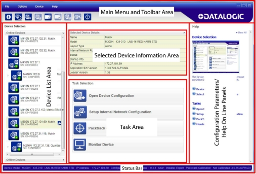
图 1 – 主窗口区域
主要特点
DL.CODE 的主要功能概述如下:
- 从不同的远程电脑同时监控设备
- 3 个不同的用户访问级别
- 实时用户和会话语言配置
- 系统配置
- 动态内容和自动页面更新
配置和监控会话
设备配置可通过在远程 PC 上运行的 DL.CODE 在单个会话中完成。一台 PC 上不能运行多个 DL.CODE 实例,并且一旦设备连接到配置程序,其他运行 DL.CODE 的 PC 就无法访问该设备。
但是,多台运行 DL.CODE 的 PC 可以同时访问监控功能。
模拟器
DL.CODE 拥有多种设备原型,可以作为离线设备加载。这样,就可以预先准备好离线配置,并在稍后将其加载到设备上。
注意: 虽然可以创建并保存离线配置 (.dlcfg) 文件 , 然后将其加载到物理设备上,但应遵循以下注意事项:
由于 图像传感器、内部存储器等存在 差异 ,强烈建议使用与待配置设备同一系列的产品。
- 以下参数组可能需要调整:手动设置图像 设置、 读取 相位、 输出 设置。
- 手动 设置 代码 设置、 良好 读取 和 数据 格式 将 予以 保留。
设备配置
要加载模拟器,请点击设备列表区域底部的“离线 设备”选项卡,打开可用模拟器的列表。
所有模拟器默认均处于离线状态。要选择阅读器,请单击其“模拟器电源”按钮图标。
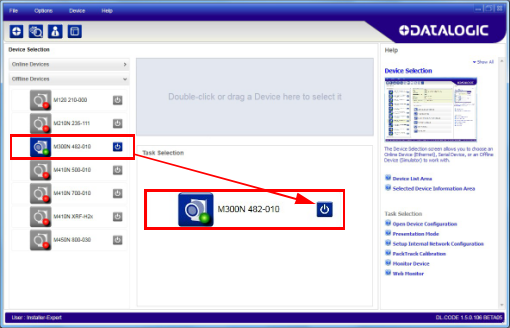
现在,您可以双击或将模拟器拖到“选定设备信息区域”中,并开始新的配置。请参阅第 3 章。
设备配置
DL.CODE 旨在通过将基本功能分组为五个主要参数组来简化标准配置:图像和代码设置(管理解码选项)、读取阶段、良好读取设置(管理操作模式)、数据格式化和输出设置(用于输出)。
图 2 – DL.CODE 配置组
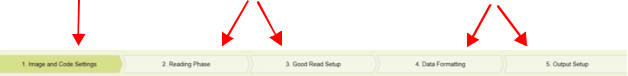
解码设置 操作模式 输出
1 图片和代码设置:
自动设置:这是一项新功能,提供一步式流程,可自动设置图像采集的光度参数(图像设置)和代码符号选择。此功能对数字图像管理 (DPM) 应用尤为有用,且无需校准。请参阅第 20 页开始的“自动设置配置”。
手动 设置:此组完全管理:
- 图像设置参数,包括用于光度测量的图像 自动 设置、多种图像设置、用于液体透镜模型的对焦 自动学习、带示波器的用于手动对焦的对焦 校准工具以及用于校准的PPI采集工具。
- 常规设置,包括处理时间和代码分级参数管理。
- 代码符号体系选择和配置,包括代码过滤参数和代码定位工具。它还包含代码 自动学习程序,用于在采集的图像上查找一个或多个未知代码符号体系。
2 读取阶段:该组负责管理图像采集的操作模式。
3 良好阅读设置:此组管理数据收集:代码收集、代码组合、代码展示或匹配代码。
4 数据格式化:此组管理输出到主机的消息。
5 输出设置:该组管理数字输出以及绿/红点。
第2章 安装
DL.CODE 分发内容
DL.CODE 程序分发包包含以下内容:
- 完成 DL.CODE 的安装
- .NET Framework(如果尚未安装)
- 技术文档,包括本手册
硬件要求
DL.CODE客户端PC的典型硬件要求如下:
- 2.00 GHz 或更快的微处理器
- 1 GB 内存
- 64 位机器需要 2 GB 硬盘;32 位机器需要 1 GB 硬盘
- 100 Base-T 以太网
- 一台 19 英寸或更大的显示器(针对 1280×1024 分辨率进行了优化)
注意: 安装 DL.CODE需要Windows安装驱动器上大约1 GB 的可用空间,因为在安装过程中 Windows 本身需要占用驱动器(例如 C 盘)上的 1 GB空间。安装完成后, 这部分空间会被部分释放(部分空间会保留安装程序备份,以便将来卸载)。
除了 DL.CODE安装文件夹所需的500 MB空间(可以更改)之外 ,还需要 其他空间。
安装
软件需求
- 以下Windows操作系统之一(32位或64位):
- Windows 8
- Windows 10
注意: DL.CODE已不再支持 Windows XP 和 Windows 7 操作系统。
• 网络浏览器:谷歌浏览器、火狐浏览器、微软Internet Explorer、Opera等。
注: 建议使用谷 歌 Chrome 浏览 器, 因为它具有卓越的性能特性
注意: DL.CODE 目前不 支持 Windows Embedded (通常用于工业 PC 和/或 PLC)。
安装 DL.CODE
注意: 从1.5.0版本开始 ,同一台电脑上可以安装多个DL.CODE版本。每个版本都会安装在各自的文件夹中,但一次只能运行一个版本。
标准安装
- 在用于配置的电脑(运行 Windows 8 或 10)上,下载 DL.CODE 迷你 DVD .zip 文件。解压缩文件,保持文件夹结构不变,然后运行start.hta文件以打开安装窗口。点击“安装 DL.CODE”链接运行安装程序,并按照安装步骤进行操作。
注意:如果需要配置串口型号,请在 DL.CODE 安装程序的欢迎窗口中勾选“RS232 串口驱动程序安装”复选框。
注意: 如果 您 需要 配置 USB型号,请在DL.CODE安装程序的欢迎窗口中选中“ Matrix USB驱动程序安装
” 复选框,并按照特定阅读器参考手册中给出的步骤进行操作。
- 安装完成后,会在“开始”菜单>“程序”栏的“Datalogic”下创建 DL.CODE 条目,同时还会生成一个桌面图标。双击桌面图标即可运行。
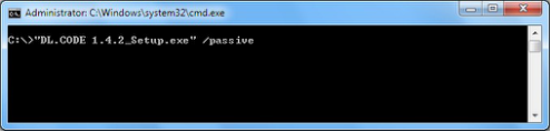
静默安装
正在卸载 DL.CODE
静默安装无需用户任何操作,可通过命令行提示符运行。安装此程序需要您拥有计算机的管理员权限。有两种安装选项:
• 静默模式:不显示任何用户界面。
• 被动模式:显示用户界面,但无需任何用户输入即可运行。
- 按 Win+R 键打开命令提示符。
- 将目录设置为解压后的 DL.CODE 安装包所在的目录。
- 使用双引号“ ”和/passive或/quiet开关调用该软件包。
正在卸载 DL.CODE
要从您的电脑中彻底卸载 DL.CODE 及其软件驱动程序,您必须按照以下步骤操作:
- 从控制面板卸载电脑上所有版本的 DL.CODE。
- 从 Windows 开始菜单 – 所有程序中的 com0com 文件夹卸载 com0com 驱动程序。
- 从控制面板卸载 USBCOMInstaller。
- 从控制面板卸载 cdcecmInstaller。
NOTE: Trying to uninstall software drivers before all versions of DL.CODE are uninstalled will cause an error.
第3章 快速入门
为了助您入门,此处提供了一份配置示例,演示了 DL.CODE 配置的基本步骤。
若要使用 DL.CODE 为您的应用配置设备,需假定已完成以下预备步骤:
- 读取设备已安装并正在运行。
- DL.CODE 已安装并正在运行(第 2 章)。
登录
首次启动 DL.Code 时,您必须通过以下选项之一登录:
- 登录
- 注册
- 使用激活文件进行离线访问
- 开始 15 天试用期
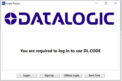
Figure 3 – Login Popup
注意:必须登录。如果您不选择任何提供的 选项, DL.Code 将 关闭 。
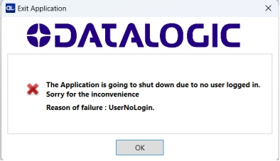
图 4 – 关闭消息
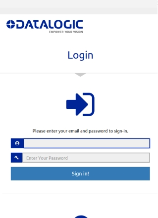
登录和注册
如果您已经拥有 Datalogic 帐户,请点击“登录”按钮,并在下方显示的字段中输入您的电子邮件和密码进行登录。
如果您还没有Datalogic账户,请点击“注册”按钮创建一个。请填写下方表格中的字段进行注册。

图 5 – 注册表
离线登录
如果您在首次启动 DL.Code 时处于离线状态,请按照以下步骤操作。
1、点击“离线登录”按钮。弹出窗口将显示机器 ID。
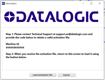
图 6 – 激活文件流程
2、请联系技术支持,并提供您 DL.CODE 版本中显示的机器 ID,以获取激活文件。
3、技术支持人员向您发送激活文件后,请使用“加载激活文件”按钮加载该文件。
注意: 上图所示的机器 ID 仅供参考。请以您DL.Code 版本中显示的机器 ID为准。
激活文件无法使用
如果您的激活文件无法正常工作,将显示以下窗口,DL.Code 将关闭。请联系技术支持寻求帮助。

15天试用期
如果您想在不登录的情况下试用 DL.Code,请点击“开始试用”按钮。这将激活 15 天的试用期。
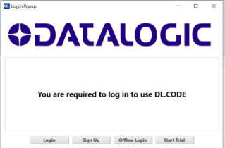
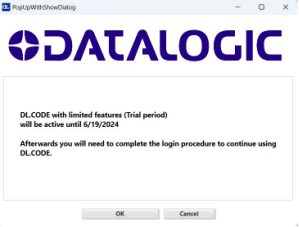
图 7 – 15 天试验
在试用期内的任何时候,您都可以选择通过在线或线下方式完成注册。
试用期结束后,您必须使用前面描述的方法之一进行身份验证,否则 DL.Code 将关闭。
注意:试用 期不可延长,且不能与同一版本或DL.Code的未来或过去版本重复使用。
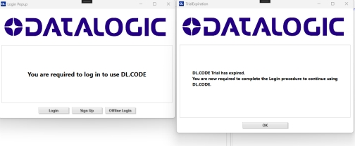
图 8 – 试验结束
以太网设备发现
注: 要查找串行型号,请参阅 第 16 页的“串行设备发现” 。 要查找 USB 型号,有关详细信息,请参阅特定阅读器的参考手册 。
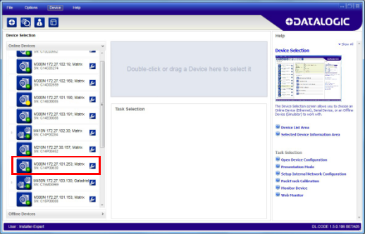
用户界面打开后会显示局域网内所有设备的列表。DL.CODE 具有设备发现功能来完成这项任务。
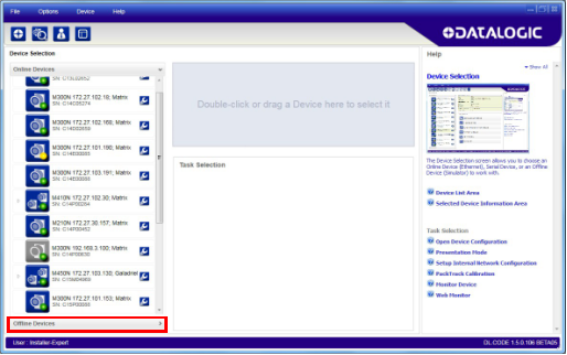
图 9 – 设备发现
发现功能还会显示不属于 LAN 的设备,并以灰色显示它们(见图 9)。
以下步骤将演示一个配置示例。
首先,必须将设备添加到局域网中,方法是将其 IP 地址与网络匹配。网络管理员应提供有效的局域网地址。
点击设备扳手图标

打开设备环境配置窗口。
根据网络需求更改以太网设置(IP 地址、子网掩码、网关地址等)。另请参见下图 10。
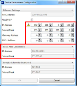
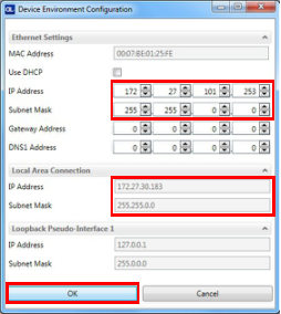
图 10 – 设备环境配置窗口
4、单击“确定”;设备将重新出现在在线设备列表中(以彩色显示),表示它现在已加入局域网,可以进行配置。新的 IP 地址也会显示出来。
5、双击或将设备图标拖入“选定设备信息”区域。设备详细信息将显示在此区域中。
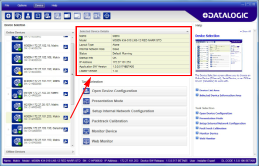
注意: 设备发现后 ,请按照解码配置参数、运行模式配置参数和输出配置参数中的说明,通过DL.CODE配置您的设备。
串口设备发现
从 DL.CODE 1.4.0 版本开始,支持串口通信,用于设备发现和配置。这使得可以通过 DL.CODE 配置专用的串口通信模型。
NOTE: Although this feature allows all devices to be configured through their Serial Interface, be aware that transmission speeds and some DL.CODE features are limited when using this interface. It is always advised to use the Ethernet interface whenever possible.
This feature is not enabled by default, so the first thing to do is to enable it through the UI Settings window.
- From the main menu open the Options
> UI Settings Window.
- Click on the Global Settings menu and scroll down to the Find Devices tab.
- Check the Enable Serial Device Discov- ery box. Scroll down to see the follow- ing selections.
- Select the Serial communication parameters according to your applica- tion.
NOTE: If you’re not sure of the Serial baud rate you can also check the Enable Automatic Device Discovery box which for serial devices will try communication at all baud rates, but only at No parity, 8 data bits;1 stop bit.
Enabling this parameter can notably lengthen Discovery time, therefore in general it is better to disable it to increase Discovery efficiency.
- Click OK to return to DL.CODE and click on the Getting Started icon.
- Open the Serial devices tab and double-click on or drag the device icon into the Selected Device Information Area.
The device is now connected to the DL.CODE Configuration environment. Configure your device through DL.CODE as described in Decoding Configuration Parameters, Oper- ating Mode Configuration Parameters, and Output Configuration Parameters.
DECODING CONFIGURATION PARAMETERS
The Decoding Configuration parameters are divided into two groups: Automatic Setup
and Manual Setup.
Automatic Setup
Automatic Setup uses up to two different algorithms for the a
utomatic setting of opti- cal, illumination and code parameters to achieve the most stable reading conditions.
Standard Automatic Setup (available on all products) can read one or more of the code symbologies from the table below. It can be set to include Image Filters if necessary.
| Enabled 1D Codes | Enabled 2D Codes | Enabled Postal Codes |
|---|---|---|
| CODE 128 | DATAMATRIX | POSTNET |
| CODE 25 | QR | PLANET |
| CODE 93 | AZTEC | |
| CODE 39 | MAXICODE | |
| CODABAR | DOTCODE | |
| INTERLEAVED 2 OF 5 | ||
| UPC/EAN | ||
| MSI | ||
| GS1 DATABAR |
The DPM Automatic Setup (available on M220X / XP, M320X and M220X-AI) is able to read one of the symbologies from the table below. It is recommended for reading diffi- cult-to-read 2D codes on Direct Part Marking applications.
| Enabled 1D Codes | Enabled 2D Codes | Enabled Postal Codes |
|---|---|---|
| / | DATAMATRIX QR | / |
NOTE: With M220X, M220X-AI, M320X, it is possible to use both Standard and DPM setup.
With all other models, only the Standard setup will be available for use.
Manual Setup
Manual Setup provides access to the complete array of optical/illumination and code definition parameters that can be fine-tuned semi-automatically and manually to obtain the best results for applications of any complexity.
NOTE: If your application requires multiple code symbologies, multiple Image settings, Code Grading or other parameter settings for decoding, then use the Manual Setup (see Manual Setup Configuration, starting on page 29).
Automatic Setup Configuration
To begin configuration, the reader must be correctly mounted so that its Field of View covers the application reading area.
NOTE: Automatic Setup is not available with Blade.
- From the Task Area select Open Device Configuration.
- The Open Device Configuration window opens showing the list of currently saved configurations (jobs) saved on the device. For new devices, the only saved job is the Default configuration. Click OK. The device enters run mode and begins acquir- ing images.
- Place the application code in front of the reader at the correct application reading distance.
- Click on the Pause button
to stop image acquisition.
NOTE: Step 4, Clicking on the Pause button is optional.
- Before proceeding with the automatic setup, you must set the focus first. Click the Focus button. A green line alerts you when the procedure is complete.
- Now click on the Start Automatic Setup button.
- The following window is displayed and the reader begins acquiring images.
NOTE: Depending on the algorithm, certain phases may not be displayed.
- At the end of the procedure the Automatic Setup Completed! message appears.
When the automatic setup is complete, a result table is displayed containing the image setup, symbology, and code properties.
Your reader is now optimized for decoding. Continue with the Operating Mode configu- ration described in Operating Mode Configuration Parameters.
Error during Automatic Setup
If the Automatic Setup cannot find the code, the following message appears.
Advanced Options
If you need more configuration options, click the Advanced Options button. Depending on the connected device, different configuration labels are displayed.
NOTE: The GUI shown below for Advanced Options is valid for firmware later than 1.12.8 and later than DL.Code 1.13.2.
Static vs Dynamic
The advanced options allows you to choose between Static and Dynamic Tuning. If your application involved moving codes, the Dynamic option must be selected to avoid a blurring effect on the image.
Figure 11 – Dynamic Tuning
NOTE: If you select the Dynamic option, two parameters must be set: Max Line Speed and Code Resolution
Autosetup Region
This option allows you to set an area of interest (ROI) on which the autosetup algorithm will focus exclusively to search for the barcode.
During the autosetup procedure, the area of interest will be temporarily hidden and shown again at the end.
At the end of the procedure, the system is configured to decode any barcodes present within the selected ROI.
Figure 12 – Autosetup Region
NOTE: The new settings are applied, so any other barcodes present in the image that can be decoded with the result of the procedure can also be decoded.
Advanced Options for M220X/M220X-AI/M220XP and M320X
The following options are displayed.
NOTE: For American and Japanese users, the label for Polarized Illumina- tion is displayed.
Figure 13 – M220X/M220X-AI/M220XP and M320X Labels
Advanced Options for All Other Models
When using a model that is that is neither M220X/M220X-AI/M220XP nor M320X, the following options are displayed.
Manual Setup Configuration
If your application requires multiple code symbologies, multiple image settings or other parameter settings for decoding, use the Manual Setup.
- Click on the Manual Setup button and press the Play icon.
- Place the Grade A Barcode Test Chart in the reading area. Once positioned, stop image acquisition by clicking on the Pause button.
- Click the Image Settings branch and then click the Image Auto-Setup button to automatically acquire the best exposure time and gain values.
- Select the Static or Dynamic Self-Tuning option; Start the Image Auto Setup and Apply to the Image Settings.
NOTE: For applications having multiple lighting or code reading conditions, up to 10 different
Image Settings can be configured by adding them with the icon.
For the next step you need to enable the Focus Calibration Tool from the Options>UI Settings Configuration tab if not already enabled.
- Now click on the Focus Calibration tab at the bottom of the window. The oscillo- scope view is shown in the bottom panel and can be used for manual focus adjust- ment.
The red line in the image panel above the oscilloscope must pass through the code. You can click and drag the red line vertically to reposition it over the code.
If the “Focus” is orange or red, the code is not focused properly. The code is focused when both the Focus and the Peak values are green.
.
You can enlarge the visual image of the code and the oscilloscope views, you can drag the Focus Calibration window up and click on the zoom image
icon repositioning it on the code.
While in run mode, manually adjust the focus until the bars relative to the code in the oscilloscope demonstrate their maximum length (focus).
You can also see the visual focus on the code view.
When focused, click Pause to stop image acquisition.
- Click the Acquire PPI button to automatically set Image Density so that reader will function correctly and to the fullest extent of its capabilities. This procedure is necessary for first time installations, or if the focal distance is changed.
NOTE: At this point it is probably a good idea to save the configuration from temporary memory to permanent memory giving it a specific name.
- Now place an application specific code in front of the reader and only click the Image Auto-Setup button to register any changes in lighting or code surface con- trast. Do not repeat Focus Calibration or PPI.
- Click on the Datamatrix symbology under the Image Settings branch (enabled by default). If this symbology is among those in your application it will be shown in the image display with its code symbology name and a green box around it indi- cating it is decoded.
NOTE: The large green box for each symbol indicates the code localization area which by default is equal to the maximum FoV. It can be resized and moved by dragging its borders with the mouse. The code must be found within this area in order to be decoded.
Add your application specific codes to the Code Settings by selecting them from the icons over the Configuration Parameters tree area. If the Data Matrix symbol- ogy is not used, then delete it from the Code Settings with the Delete icon.
If you don’t know the code type, you can use the Code Autolearn feature by click- ing on the Autolearn icon.
See “Code Autolearn Feature” on page 58 for details.
- For each symbology set the relative parameters according to your application.
OPERATING MODE CONFIGURATION PARAMETERS
Reading Phase
- Select your application specific Operating Mode from the icons over the Configu- ration Parameters tree area: Continuous, One Shot, Phase Mode or PackTrack.
- Configure the relative Operating Mode parameters from the Reading Phase parameters panel. Different groups will appear in the panel depending on the selected icons over the Configuration Parameters tree area.
CAUTION: If the same signal activates multiple events with the same edge, those events are fired in a random order.
If the same channel activates multiple events with the same string, those events are fired in a random order.
AVOID doing this action. The reader may not work properly, the result is not predictable!
![img]() Good Read Setup
Good Read Setup
OPERATING MODE CONFIGURATION PARAMETERS
- Select your specific data collection type from the icons over the Configuration Parameters tree area: Code Collection, Code Combination, Code Presentation or Match Code. Not all data collection types are available for all Operating Modes; for example PackTrack Operating Mode only supports Code Combination. Incom- patible data collection types will be shown in gray and cannot be selected.
The following example shows Code Combination. By default, the Expected Codes (when more than one code type is selected), are in logical AND, which means that all codes are required to be decoded to produce a Good Read condition.
- If a Good Read condition should be produced when any single code is decoded, independent from the others, then they need to be combined in logical XOR. To do this, drag the code icon(s) from their relative Expected Code box into the Expected Code box of the XOR combination you wish to create. Then delete the empty box by selecting it with the mouse (highlighted) and pressing the delete key on your keyboard.
To create a logical AND condition from a logical XOR, create a new Expected Code box using the Add icon. Then drag the desired code from one box to the other.
OUTPUT CONFIGURATION PARAMETERS
Data Formatting
- Configure your application specific Data Formatting Message(s) from the Configu- ration Parameters tree area: Message 1, Message 2, etc.
You can add fields to the output message by clicking on the icons above the Message Field area. They will be appended to the message. You can drag them to position them between other fields in the message so that the output message is ordered according to your application requirements.
Each field has its own relative configuration parameters in the parameters panel.
Output Setup
OUTPUT CONFIGURATION PARAMETERS
- Configure your application specific Digital Output(s), Green/Red Spots and 360° Feedback (depending on Matrix model) from the Configuration Parameters tree area: Output 1, Output 2, etc.
NOTE: Save the configuration from temporary memory to permanent mem- ory, overwriting the previously saved configuration.